Improving mobile signal coverage across all 4 UK Networks in two locations in Bedfordshire

The Challenge
A supplier of cut flowers was looking to improve the indoor mobile coverage within the office and working areas of their factory in Sandy, Bedfordshire. Coverage was required in two locations and across all four UK Networks: O2, EE, Vodafone, and Three.
It is worth mentioning that the O2 and Vodafone signals were not identified at all at the small outbuilding in the area before installation. And there was really poor coverage in signal strength and quality at the main building.
The Solution
Based on floor plans, two solutions were considered. One is based on CEL-FI GO G41, and the second is based on CEL-FI QUATRA 4000e. UCtel conducted a site survey to determine the available signals on the roof of the building and to design the system which will be installed.
UCtel strategically placed four Coverage Units to achieve the best possible signal coverage in the factory.
Due to the building’s interior design, the use of structured cabling was the key consideration and so the CEL-FI QUATRA system of one Network Unit and four Coverage Units was installed.
The Installation
UCtel recommended using the CEL-FI QUATRA 4000e to broadcast the external signal around the main building and CEL-FI GO G41 for the small outbuilding.
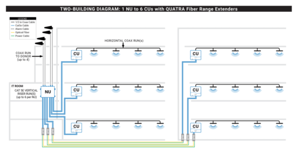
- CEL-FI QUATRA 4000e System Architecture
UCtel deploys solutions from Nextivity. Nextivity manufactures the CEL-FI suite of cellular coverage solutions which are designed to optimize mobile signal coverage within buildings and vehicles. CEL-FI is unconditionally network safe, preventing interference with mobile operator networks. In the UK CEL-FI products are license-exempt and fully comply with Ofcom’s UK Interface requirement 2102 (IR2102). CEL-FI QUATRA is a distributed antenna system (DAS) hybrid solution that combines the strength of passive and active DAS technologies to deliver high-quality mobile signals in buildings. CEL-FI QUATRA delivers a mobile signal up to 1000x stronger than analogue, utilising CAT 5e/6 cabling for RF and power over ethernet, with no signal attenuation right to the perimeter of the building.
The CEL-FI QUATRA solution consists of a donor antenna that is installed on the roof or outdoors where the mobile signal is strongest, a network unit (NU) that amplifies and digitizes the mobile signal, and a network of coverage units (CUs) that are placed around the building to rebroadcast the boosted signal. Passive DAS segments can optionally be added to distribute the signal around the building if required. The diagram below shows an example of the QUATRA 4000e architecture.

- CEL-FI GO G41 System Architecture
The CEL-FI solution needs to receive the best available donor signal from outside and transport the signal through low-loss cable to the network repeaters that then distribute the signal through indoor antennas.
A system comprises:
● Donor antenna installed where it can obtain the best donor signal
● Low-loss cables
● Repeaters to receive donor signal and boost it
● Internal antennas to broadcast the boosted signal
- Donor Antenna Install Locations
One directional donor antenna was mounted on the roof of each location requiring coverage, these were secured onto existing structures and positioned aiming for the most suitable nearby cell tower. Images of both of these can be seen below.
- Hardware ( QUATRA 4000e) Installation Location
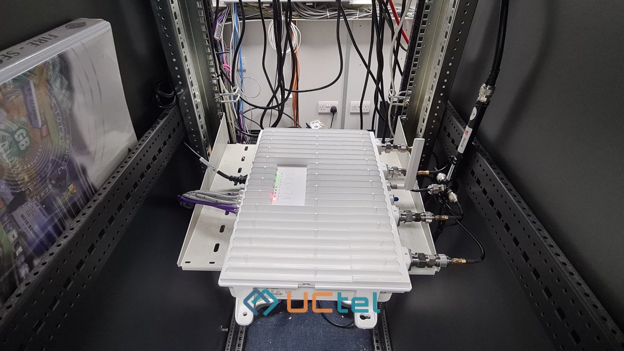
The QUATRA 4000e network unit was installed within the comms cab located on the first floor of the main building:
- Hardware (GO G41) Installation Location
Four G41 units (one per network) were installed on the wall within the small outbuilding of the site.
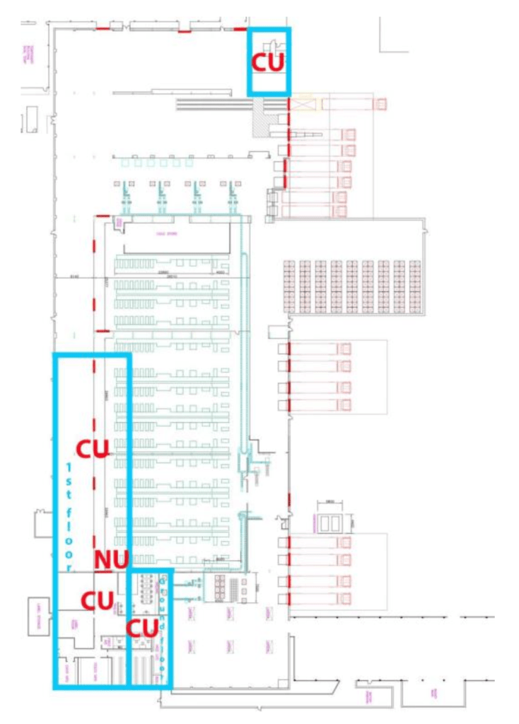
- Main Building QUATRA 4000e Coverage Unit Locations
Four coverage units were installed to achieve the best signal coverage possible. The floor plans below show the locations of the units:

CU = Coverage Unit
NU = Network Unit
The Results
The work conducted by UCtel achieved excellent mobile signal coverage across all four UK Networks.
The signal level has been vastly improved across all networks within the required areas of the factory.
- Post Install Signal Findings at the small outbuilding
The table below shows the readings before installation (N/A refers to signal not having been identified ):

The table below shows the readings post installation:

The table below shows download and upload speed after the system was commissioned:

- Post Install Signal Findings at the main building
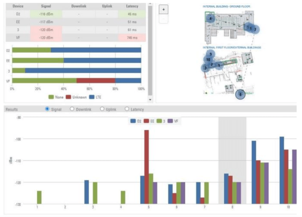
The reading below demonstrates the poor signal in terms of both strength and quality at the main building before installation:

The readings below show the signal level improvements within the main building:
Download speed from the main building can also be found below.
The client was delighted with the work UCtel conducted and the associated improvements in mobile coverage and, subsequently, ordered an installation at another site.
